Production Firmware : 17 November 2020
EXPERIMENTAL Firmware: 16 July 2021
Dragon Link 915 MHZ Advanced users CLICK HERE for information on system differences.
IMPORTANT: We strongly recommend looking at the Radio Modem / Telemetry features of the Dragon Link system. Even though it is not required, this feature already built into the Dragon Link system gives you a lot more capability, features, and safety. You can set up features such as Moving Map, flight instruments, flight planning, and a lot more. These things can allow you to fly your plane home in case of lost video. You can always set up the system in basic mode, and enable telemetry and other more advanced features later on. Just be aware they are there whenever you want to use them !
CLICK HERE FOR RADIO MODEM / TELEMETRY SETUP GUIDE
915 MHZ IMPORTANT !!! CLICK HERE FOR 915 MHZ SPECIFIC System Differences
Although not required, we strongly recommend downloading the latest firmware and updating your system, as we have frequent updates to enable new features and capabilities. It is NOT required to ever connect this system to a computer. The Dragon Link system will give you incredible performance just as it is without update and without ever connecting to a computer, but using the configuration software will open up a huge number of advanced features like built in Radio Modem, Telemetry and other very useful features.
IMPORTANT !!! Click here for proper mounting of receiver antenna on your plane or copter.
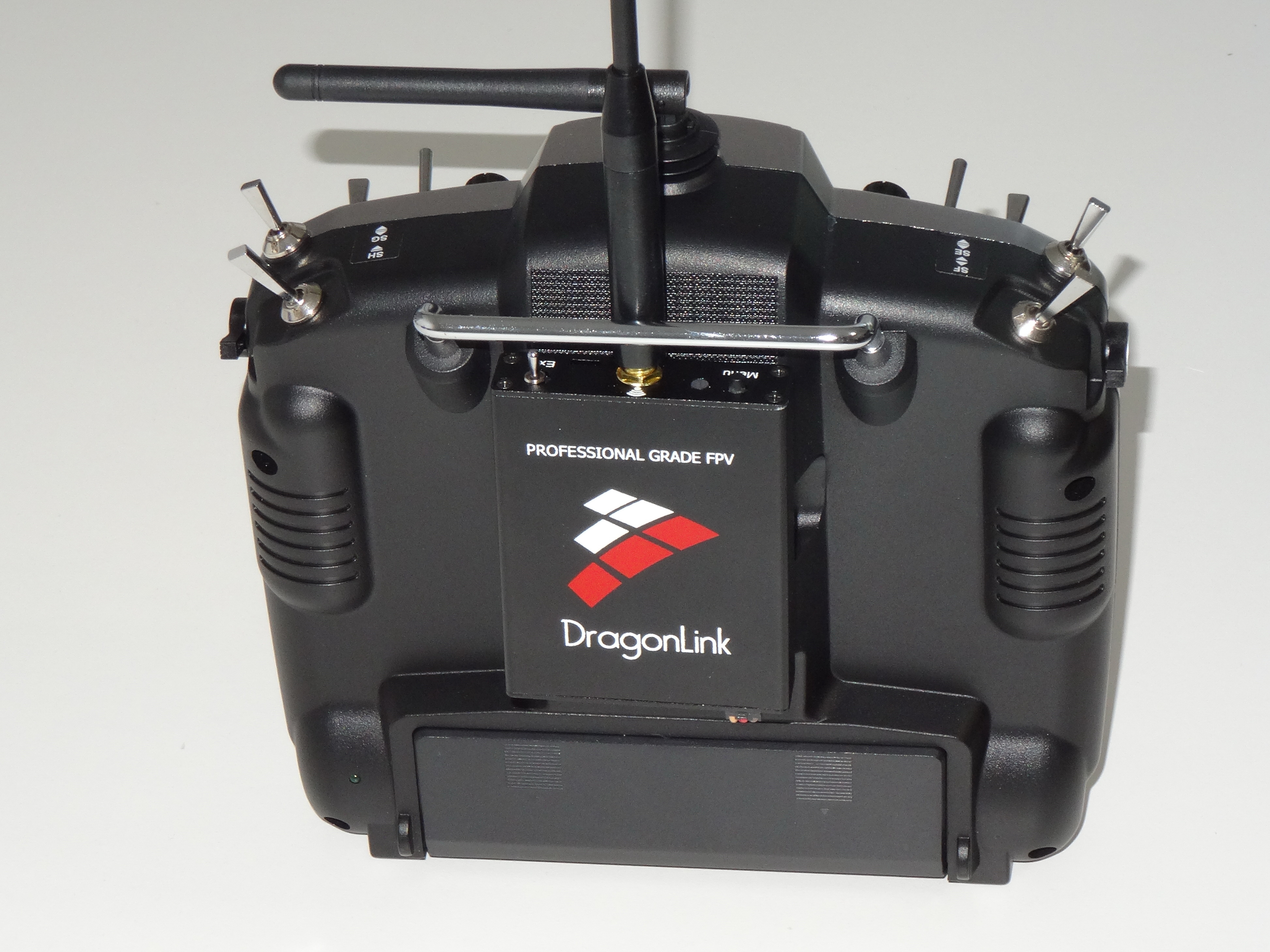
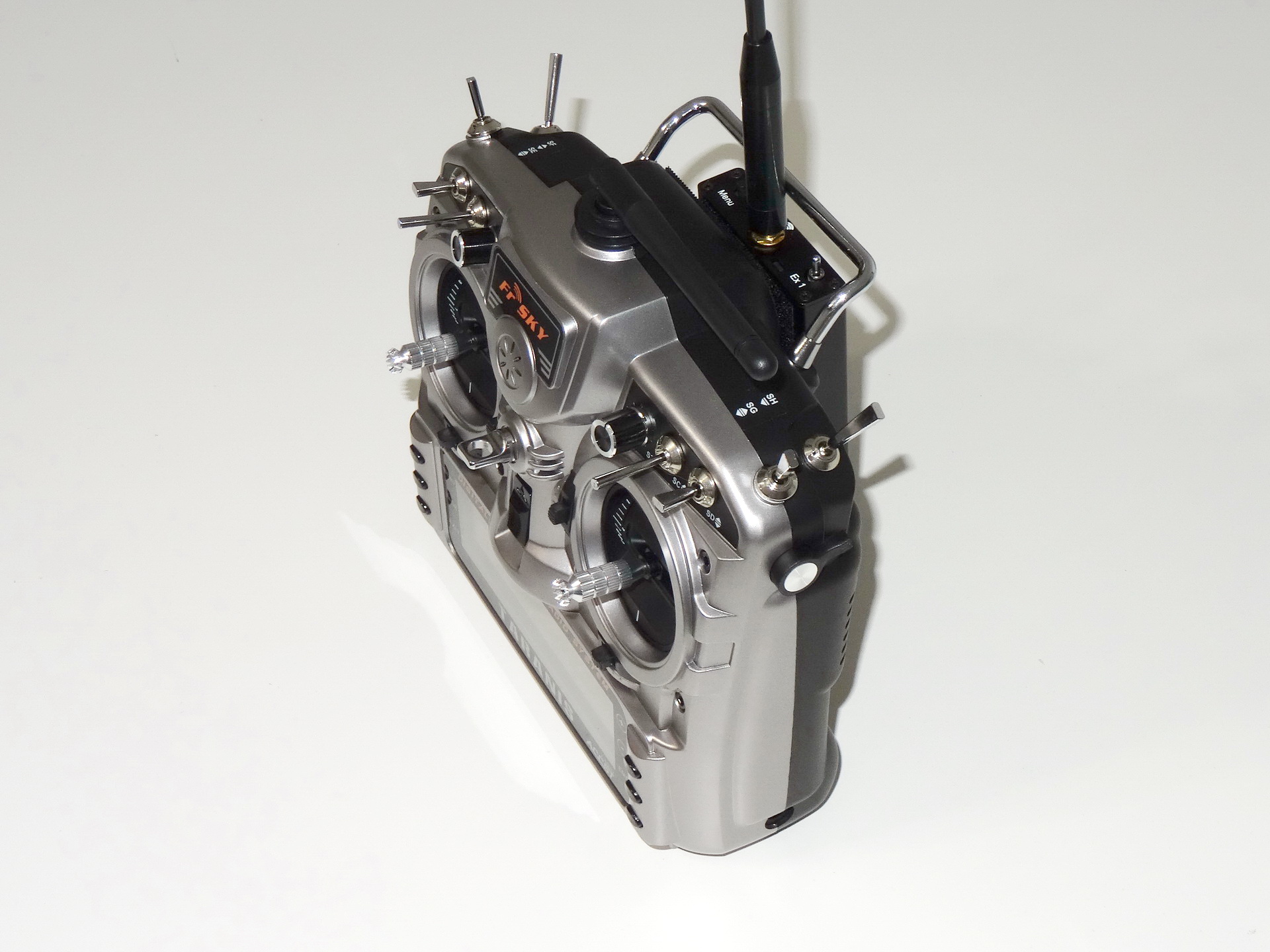
STEP 1 - Mount Dragon Link Transmitter to your RC transmitter: We suggest using Velcro to attach your Dragon Link transmitter directly to the back of your RC transmitter. This results in the most compact, convenient, and lightest installation possible. Do not worry about keeping the Dragon Link TX antenna vertical while you fly, this would only become a factor in very long range flying, 20 Kilometers or more. For those that want a mounting bracket, we sell an optional mounting bracket that screws to the thin metal handle that many RC transmitter have.
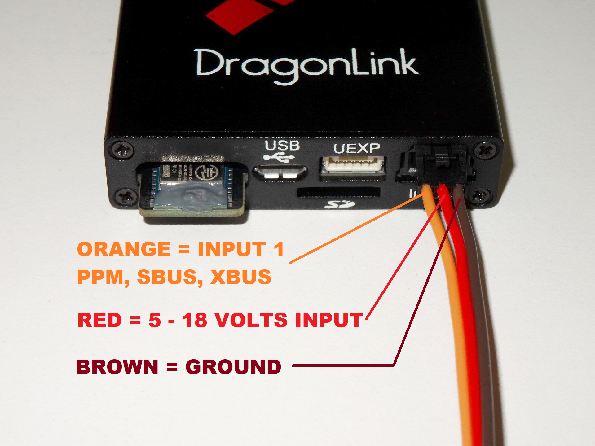
STEP 2 - Connect Dragon Link Transmitter INPUT 1 to your RC Transmitters PPM output ( DSC Port, Trainer Port, or RF Module Pins ) with Included Cable: When you purchase Dragon Link, you will have the option to choose what kind of connection cable you want. Simply plug the cable into INPUT 1 on your Dragon Link Transmitter and do the following for each different type of RC transmitter:
Connect Dragon Link to your RC transmitter, and assure that you have a GREEN LED's on the Dragon Link transmitter. The GREEN LED's indicates that you have both power and valid PPM signal from your RC transmitter, and is required before proceeding to the next step. The Dragon Link will not bind or work until the Transmitter LED's turns GREEN when you turn the system on. RED LED's indicate there is power, but no PPM signal. If you have a RED LED, make sure your Trainer or DSC Port is activated in your RC transmitters computer menu.
STEP 2 - CHANGE ID ON TRANSMITTER: Hold down the BIND button on the Dragon Link Transmitter and power the Dragon Link Transmitter on. Continue to hold down button for approximately 5 seconds while the LED's on the transmitter cycles through its different colors. When the LED's on the transmitter TURNS RED, Release the button, the LED's will continue to flash RED, and you will hear 4 beeps, the ID is now changed. Power off transmitter.
STEP 3 - BIND RECEIVER TO THE TRANSMITTER: Hold down the BIND button on the Transmitter, and power the Transmitter on. Continue to hold down the button for approximately 3 Seconds until LED's turns BLUE, then release the button. The LED's will flash BLUE, and you will hear two repeating beeps, this indicates you are in binding mode. Power on the recever, the GREEN and BLUE LED will flash indicating a successful bind. Power off both Transmitter and Receiver, then power them on again. You should see a SOLID BLUE LED on the receiver, this indicates a valid, steady RC link is being received by the receiver. You should now see SOLID BLUE LED's on the transmitter, the SOLID BLUE LED's on the transmitter indicate that a bidirectional telemetry link is being received from the receiver.
STEP 4 - SET FAILSAFES: Both the Transmitter and Receiver must be powered normally with a VALID LINK ( SOLID BLUE LED on the receiver ) Set the controls where you want them to be in a failsafe ( lost signal ) condition, and push the BIND button on the Transmitter for one second, the LED's on the transmitter will turn GREENISH BLUE, and you will hear a tone from the transmitter, which indicates failsafe has been set.
STEP 5 - RANGE TEST: Set the Dragon Link Transmitter into Micro Power Range Test mode: Hold down the BIND button and power on the transmitter. In approximately 3 seconds the LED's will turn GREEN, release the bind button when the LED's turn GREEN. The LED's will now flash GREEN, and you will hear a slow single beep, this indicates Micro Power Range Test mode. Set the Transmitter on a table, antenna vertical, and walk away with your plane or copter held at a normal level with its antenna also vertical. You should see RED, GREEN, and BLUE LED's illuminated on the receiver. Walk away until the system starts to go into constant failsafe's. Failsafe is indicated by the BLUE LED on the RECEIVER turning off. Do NOT stop on the first failsafe, but walk away until the receiver is in failsafe 50 % of time ( BLUE LED on the receiver flashing on and off about 1/2 of the time. ) You should get at least 10 meters, or 30 feet distances away from the transmitter before this happens. If the system goes into constant failsafe at distances significantlyless than 30 feet, DO NOT FLY until you have corrected the problem and get a good range test. Getting a Micro Power Range test of up to 60 feet is OK, but if you get a test further than 60 feet, this indicates the transmitter is in normal power mode, and do not have a valid range test, assure transmitter is in micro power mode and start over. NOTE: On small copters or planes that will not be flown more than 5 Kilometers distance, you can accept a micropower range test of 15 feet.
STEP 6 - FLYING: You will now have basic, very reliable, and very long range RC control and can fly FPV further and safer than you ever have before. Be aware that long range RC control is only a small part of what the Dragon Link advanced system will do. We strongly encourage you to connect the transmitter to your computer via any standard Micro USB cable, and bind it to your smartphone or tablet, and set up alarms, see a map of where your plane is, see how fast it is going, etc etc. to take full advantage of what this system will do. Complete instructions will continually added below as we develop new features and capabilities.
TELEMETRY SETUP (OPTIONAL ): You can set up telemetry any time, if you choose to do this see the different telemetry setups and options available to you Under Dragon Link Advanced CLICK HERE.
WiFi / Bluetooth ( OPTIONAL ): Setup instructions and firmware upgrade CLICK HERE.
LED INDICATIONS ON DRAGON LINK TRANSMITTER:
1. SOLID BLUE LED's = Good telemetry signal being received by the Transmitter from the receiver. Will flash GREEN with each telemetry packet lost.
2. SOLID GREEN LED's = Transmitter operating normally with valid PPM input, but NO telemetry being received. ( normal indication if receiver is turned OFF )
3. SOLID RED LED's = No PPM signal being received by the Dragon Link Transmitter. Check RC transmitter settings, trainer port / DSC settings, and connections to RC transmitter.
4. WHITE FLASHING LED's = Hardware error codes, contact us through email support for assistance.
5. FLASHING YELLOW LED's = User configurable Alarms, Combined with tone, to alert you if certain parameters are exceeded. Battery Alarm, RSSI Alarm, etc. etc.
TRANSMITTER MODES: These modes can quickly be accessed at the filed by Holding down the BIND button upon power up.
1. MICRO POWER MODE: FLASHING GREEN LED, 1 BEEP REPEATING SOUND PATTERN
2. BINDING MODE: FLASHING BLUE LED, 2 BEEP REPEATING SOUND PATTERN
3. SERVO TEST MODE: FLASHING YELLOW LED, 3 BEEP REPEATING SOUND PATTERN
4. CHANGE ID: FLASHING RED LED, 4 BEEP REPEATING SOUND PATTERN
5. EXIT USB TELEMETRY MODE: FLASHING WHITE LED, 5 BEEP REPEATING SOUND PATTERN
TRANSMITTER SPECIFICATIONS:
Input Voltage: 5 - 18 Volts ( Any 2 - 4 Cell Lipo ) of 1000 mah or larger will work perfectly.
Power Usage: About the same as a normal RF module, most RC systems will work for hours when the Dragon Link transmitter is powered and operating.
MICRO RECEIVER SPECIFICATIONS:
Fully Compatible with ALL flight controllers, autopilots, and airborne devices.
Input Voltage: 5 - 9 Volts
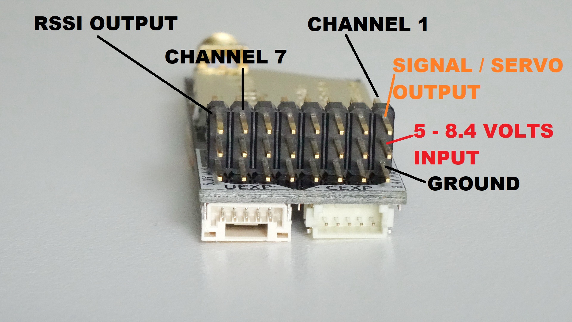
Channels 1 - 6 Standard Servo ( PWM ) outputs by default
Channel 7: PPM output by default
Channel 8: RSSI output by default.
MANY additional modes and features, see the .pdf manual, and also receiver software linked above for more information.
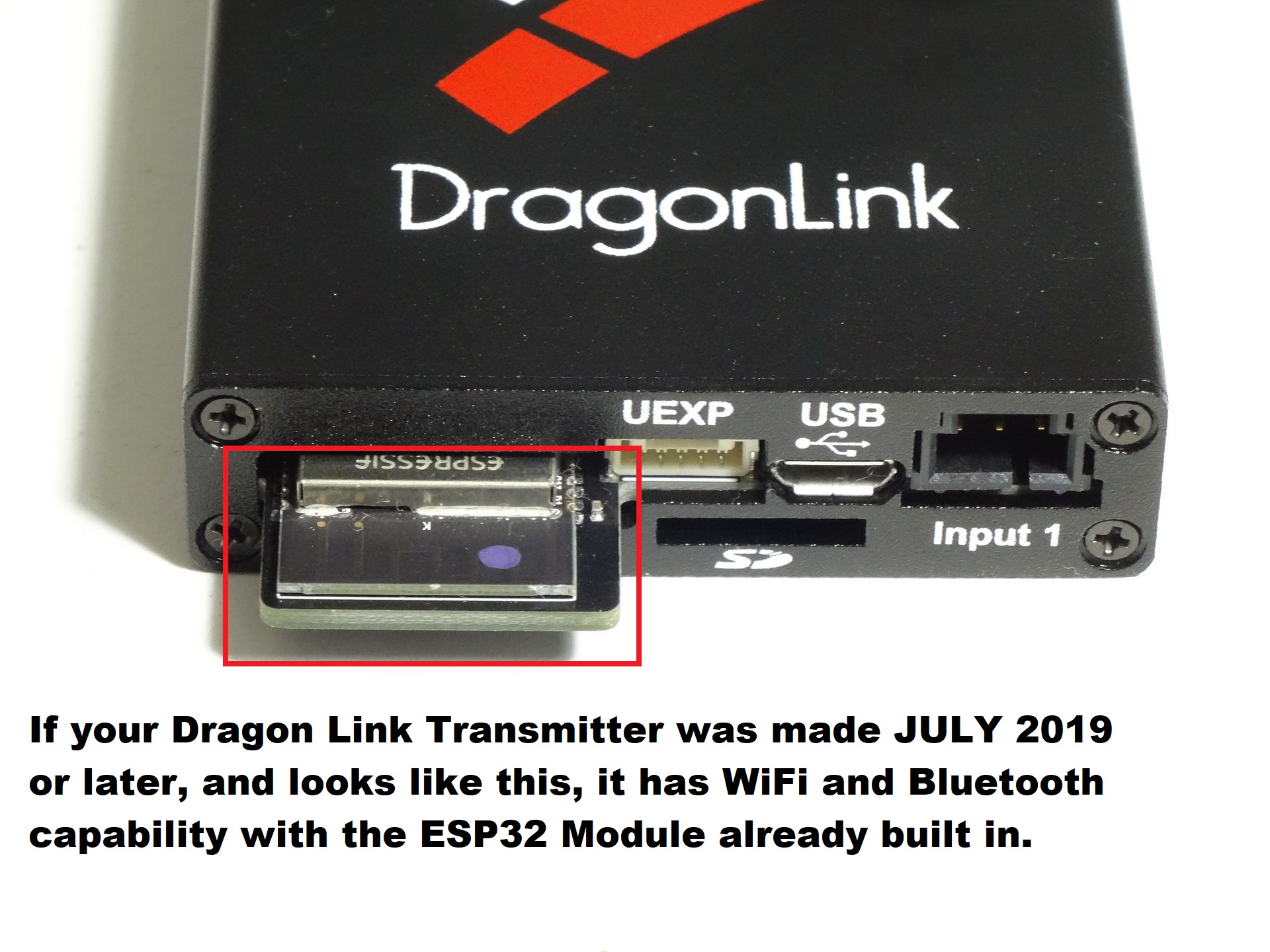
OPTIONAL: WiFi / Bluetooth Setup. If your transmitter was made JULY 2019 or later, and has a BLACK PCB part sticking out the bottom of the transmitter as shown in the picture to the left, it has a firmware up-gradable ESP32 WiFi / Bluetooth module built in. If you transmitter does not have this type of module, you can get a plug and play WiFi / Bluetooth module from our webstore http://www.fpvpro.com/wifi-bluetooth-module
CLICK HERE FOR WiFi / Bluetooth setup and firmware upgrade instructions.
WiFi Settings: NAME: DragonLink PASS: DragonLink
IP ADDRESS: 192.168.1.1 PORT: 14550