Dragon Link OSD Setup Instructions:
Download the firmware package below for the firmware and configuration utility. All Dragon Link OSD's shipped after January 2018 already have the latest firmware on them. Updating the firmware on OSD's that have shipped after January 2018 again is NOT recommended as it will serve no benefit, and could possibly introduce errors. Only update your OSD's firmware if it was shipped prior to January 2018.
Dragon Link OSD Firmware and Configuration Utility: Click here to download OSD Firmware Version 2.72
HARDWARE SETUP - Connect your OSD
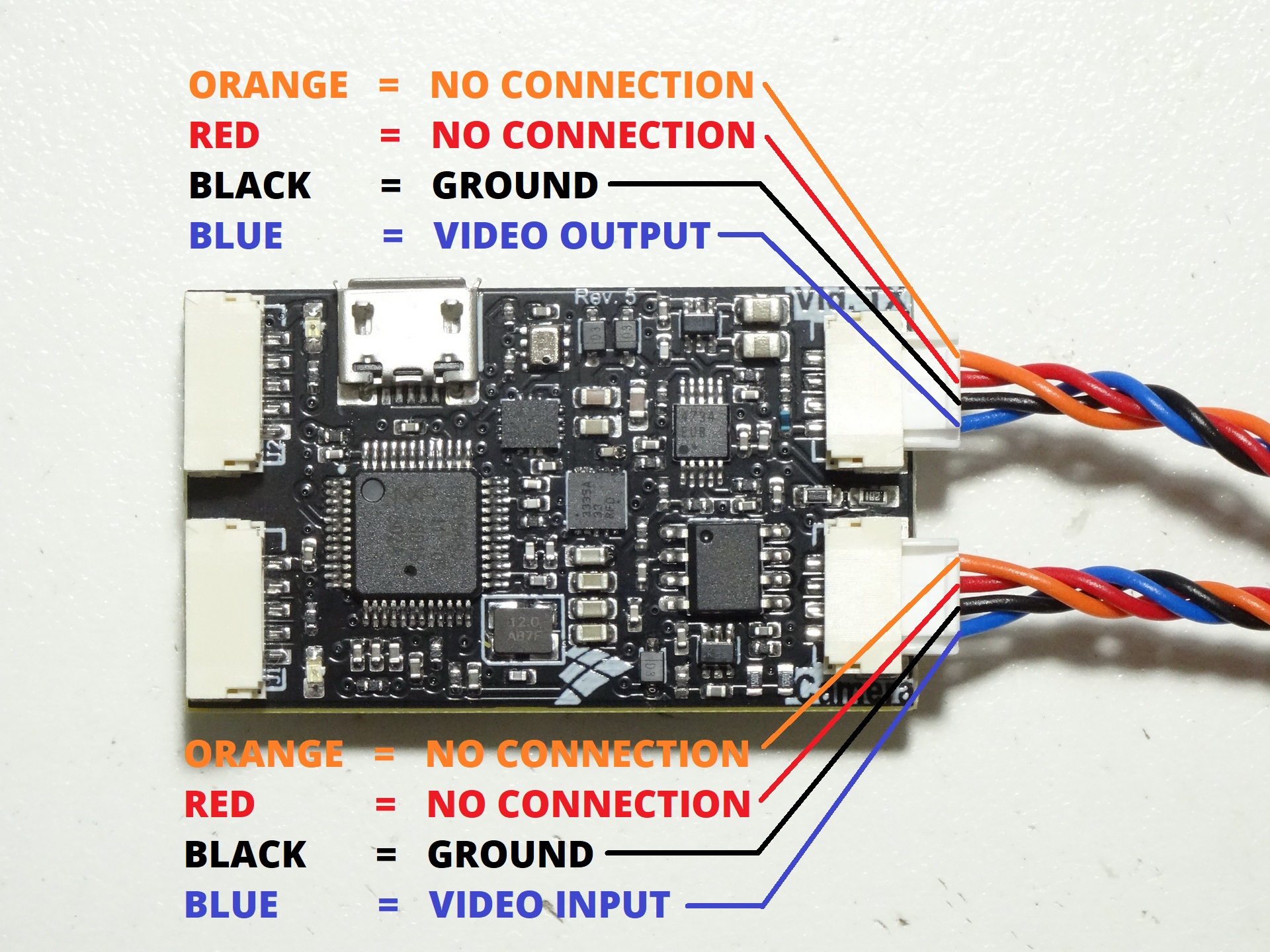
STEP 1: Connect your video camera video output using supplied cable and connect it to the CAMERA connector as shown in the picture to the left.
STEP 2: Connect your video transmitter video input using the supplied cable and connect it to the Vid TX connector on the OSD as shown in the picture to the left.
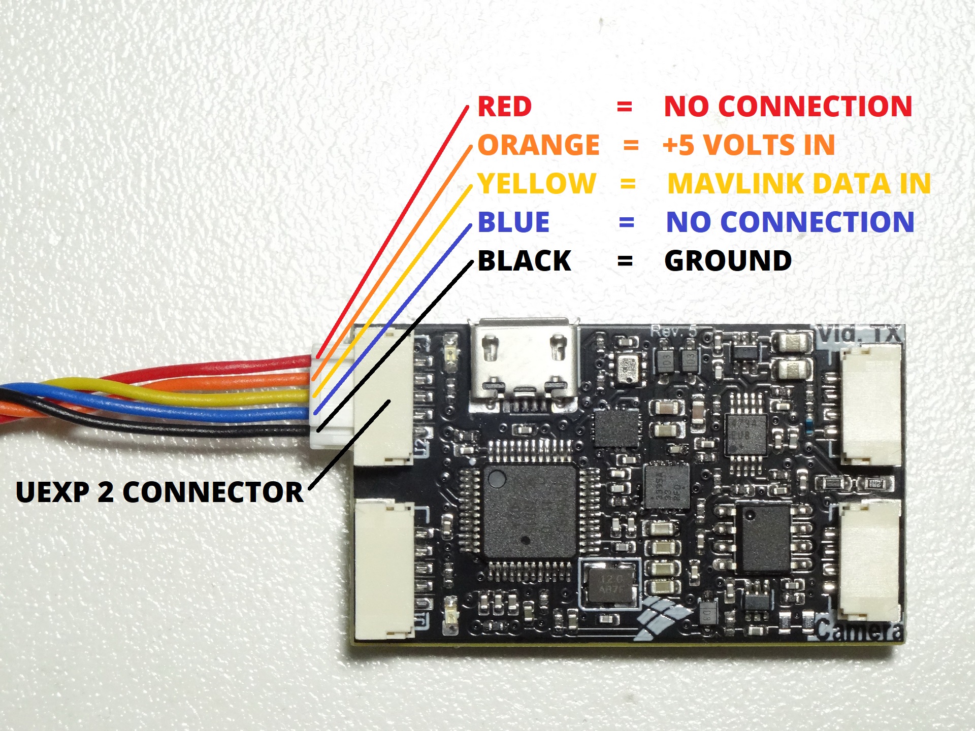
STEP 3: Connect a regulated 5 - 6 volt power source from your flight controller or other regulated 5 - 6 volt source to the orange wire of the supplied 5 pin UEXP data cable as shown in the picture to the left. WARNING: Power must be 5 - 6 volts, connecting higher voltages will burn out the OSD.
STEP 4: Connect the Dagon Link OSD to a serial port of your flight controller using the Black and Yellow wire of the supplied 5 Pin UEXP data cable as shown in the picture to the left. You can connect the OSD to any available serial port of your flight controller. For this example, we are using serial port 1.
You have now connected the Dragon Link OSD to your system, you should see a BLUE and GREEN LED on the OSD as well as see the text overlay on your video when you power the system on. Proceed to the next section below to configure your OSD.
OSD Settings and Configuration
STEP 1: Connect a standard Micro USB cable to your OSD and run the Dragon Link GUI configuration program on a Windows Computer.
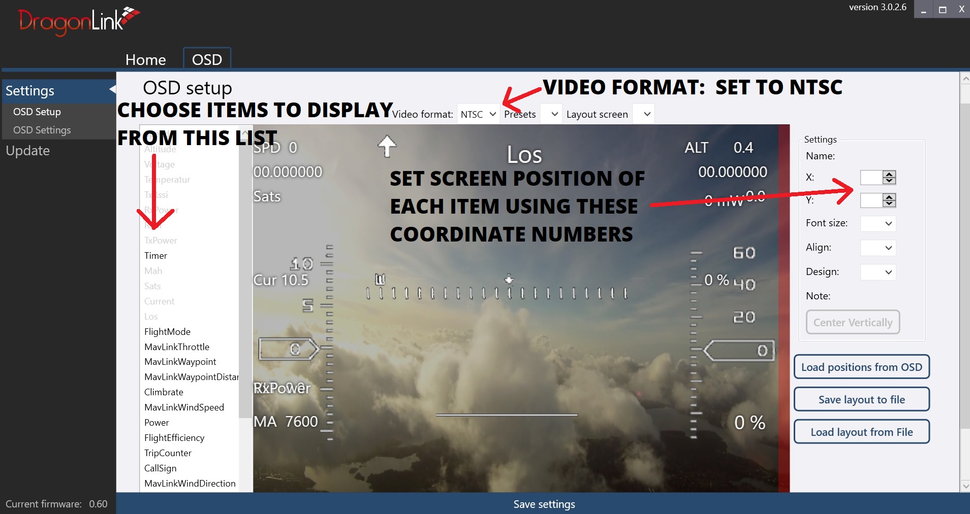
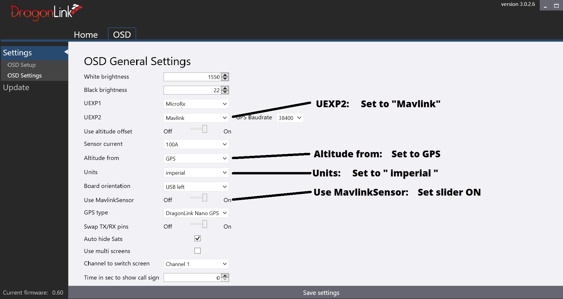
STEP 2: You will see a new tab at the top of the screen appear called " OSD ", click it and you will see the picture to the left appear.
STEP 3: Click " OSD Setup " on the left to enter Video Screen Setup
STEP 4: Click the " SAVE SETTINGS " bar at the bottom.
STEP 5: Click "OSD Settings " on the far left of the screen to enter the OSD options list.
STEP 6: Click the " SAVE SETTINGS " bar at the bottom.
ArduPilot / Mavlink Configuration
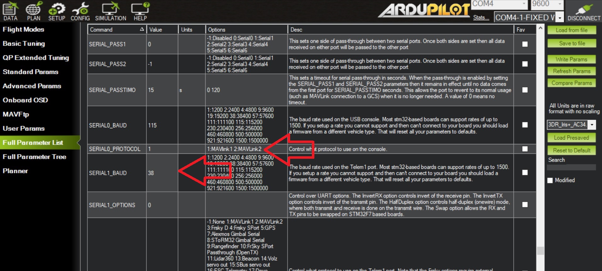
You can select any serial port on your flight controller to output Mavlink data, in this example we have connected the OSD to serial port 1, so we will configure serial port 1 for data output to the OSD. The screen capture from the left is configuring ArduPilot using Mission Planner software.
STEP 1: Set " SERIAL1_PROTOCOL " to 1, which is Mavlink 1 protocol.
STEP 2: Set " SERAIL1_BAUD " to 38, which is 38,400 baud.
STEP 3: Click the WRITE PARAMETERS box on the right.
STEP 4: Power on the system, and check that valid data is shown in the Dragon Link OSD.
END